
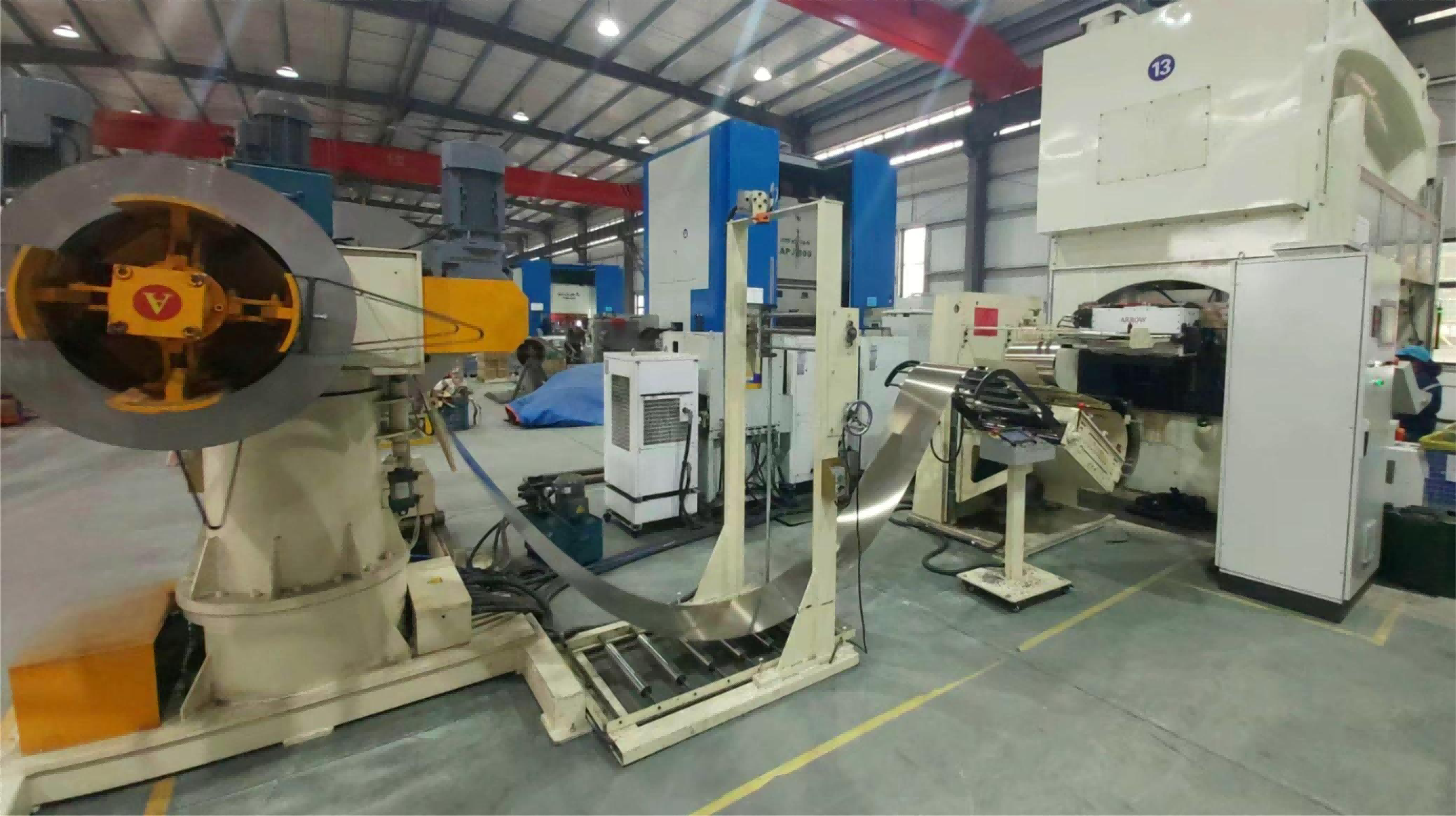
Progressive Stamping for Motor Laminations: A Complete Guide
Every electric motor begins with thin steel. Before windings, shafts, or housings exist, hundreds of precision laminations must be stamped from electrical steel — and for high-volume motor production, progressive die stamping is the process that makes it economical. This guide covers the complete workflow, from coil preparation to stacked, curled, and inspected motor cores.
Why laminations exist at all
A solid iron core would carry massive eddy currents, wasting energy as heat. Laminations — thin insulated sheets stacked together — interrupt those currents. That single design decision is why motor manufacturing is inseparable from precision sheet-metal stamping.
The progressive stamping process, step by step
Step 1. Coil preparation and feeding.
The line starts with a coil of non-oriented silicon steel. A decoiler and a high-speed servo feeding system advance the strip into the press with positioning accuracy measured in hundredths of a millimeter. Feed speed, not press speed, is usually the ceiling on overall line rate — which is why servo-driven feeding with multi-roller leveling is worth specifying carefully.
Step 2. In-die progression.
The strip passes through a multi-station progressive die. At each press stroke, pilots align the strip on pre-punched reference holes, stations progressively pierce slots, notch the inner and outer profiles, and form interlocking tabs, and the final station cuts the finished lamination free. A single die may run 10 to 20 stations. The interlock tabs formed in-die stack laminations automatically as they fall — this is how lamination stacking becomes free.
Step 3. Lubrication and burr control.
Precision mist oiling applies a micro-thin film of lubricant — enough to extend die life and reduce burr formation, little enough to avoid contaminating the insulating coating of the lamination. Burr height is a headline quality metric: excessive burrs can pierce sheet insulation after stacking, creating inter-laminar shorts and elevated core loss.
Step 4. Stacking, welding, and curling.
Depending on the product, interlocked stacks accumulate in-die to a programmed height, welded cores pass through automatic shear-and-weld stations for seam or laser joining, and stator cores for certain motor families proceed to a curling process — the laminated strip is curled into its final circular form, a specialty process used in high-efficiency and outer-rotor motor designs.
Step 5. Pressing and inspection.
Finished rotor and stator cores undergo pressing-inspection to verify stack height, outer and inner diameters, and interlaminar integrity. For rotor cores destined for die casting, dimensional checks feed directly into the downstream casting cell.
Key quality metrics in lamination stamping
1. Burr height — controls interlaminar shorts and core loss. 2. Slot pitch accuracy — affects winding fit and cogging torque. 3. Stack height consistency — drives motor-to-motor performance variation. 4. Coating integrity — determines the insulation resistance of the finished core. 5. Scrap rate — material is the dominant cost in lamination production.
Electrical steel is a significant share of a motor's bill of material. A stamping line that holds tolerances tightly keeps scrap — and per-motor cost — down.
Speed or accuracy? You need both
High-speed presses for laminations run from roughly 200 to over 800 strokes per minute. The equipment decisions that protect quality at those speeds are unglamorous but decisive:
1. Servo feeding with closed-loop position correction. 2. In-die sensors detecting strip misfeed or slug return. 3. Hydraulic in-die leveling systems maintaining flatness through the run. 4. Servo-driven rotary positioning for consistent lamination orientation. 5. Automatic lubrication metering.
Automating the full stamping cell
A modern motor core stamping automation system integrates strip preparation, feeding, lubrication, leveling, pressing, inspection, and stator core curling into one continuous flow. Compared with standalone presses and manual material handling, integrated cells deliver higher effective output with less idle time between coils and stacks, traceable quality data per batch, lower labor exposure to press operations, and consistent output feeding downstream rotor die-casting and motor assembly lines.
Frequently asked questions
Q: What speed can progressive stamping achieve for motor laminations? A: Production lines commonly run 300 to 600 strokes per minute depending on lamination size, material thickness, and die complexity; specialized lines exceed 800 strokes per minute.
Q: What steel thickness is used for motor laminations? A: Typically 0.2 to 0.5 mm for most motor families. Thinner laminations reduce core loss but increase stamping difficulty and stack counts.
Q: Can one line produce both rotor and stator laminations? A: Yes, with quick-change die setups. Changeover time is a key line specification for plants running multiple motor models.
Q: What is stator core curling? A: A forming process where a laminated strip is curled into a cylindrical stator core — used in certain high-efficiency and outer-rotor motor designs, and available as an integrated stamping-line station.
Planning a lamination stamping project? Explore our motor core stamping automation systems — from servo feeding and mist oiling to rotary positioning, in-die leveling, pressing inspection, and stator core curling. Send us your lamination drawing and target volume for a process proposal.
Product page: https://www.ldmotortech.com/en/products/stamping Related reading: rotor die casting cells at https://www.ldmotortech.com/en/products/die-casting and motor assembly lines at https://www.ldmotortech.com/en/products/motor-assembly