The performance ceiling of a permanent magnet motor is set, in essence, by its magnets. Magnet shape is the foundation of magnetic circuit design: it determines flux distribution, torque output, efficiency, vibration, and manufacturing cost. For motor manufacturers, choosing the shape is only half the problem. The other half is producing rotors with those magnets, at volume, without chipping, polarity errors, or flux drift.
This article covers both sides: the six magnet shapes used in PM motors and where each fits, the selection logic that ties shape to rotor structure, and what your motor assembly line must be able to do once the choice is made.
Six magnet shapes and where they fit
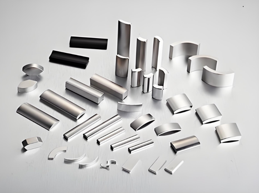
1. Arc or tile magnets. The most common shape for sintered NdFeB motor magnets. The curved face matches the rotor surface, keeping the air gap even and the magnetic field stable, but it requires precision grinding to hold the arc tolerance. Found in small and medium power motors: DC motors, permanent magnet synchronous motors, EV traction motors, fan motors.
2. Square or rectangular magnets. Simple geometry, low machining difficulty, easy multi-pole magnetization, and easy batch assembly make this the cost-effective choice. The trade-off is slightly higher air-gap flux harmonics, which matters little except in extreme quietness or low-ripple designs. The standard choice for interior permanent magnet (IPM) rotors, linear motors, stepper motors, and cost-focused appliance motors.
3. Ring magnets. Available as bonded radial multi-pole rings or sintered segmented rings. Excellent concentricity, even field distribution, and radial multi-pole magnetization in one piece, with no assembly of segments. The limits are residual field at the geometric neutral line and lower material utilization. Sintered full rings are complex and costly, so they go into high-end precision devices: coreless motors, pump motors, encoders, precision sensors.
4. Parallelogram or skewed tile magnets. A custom shape whose angle is designed to optimize the back-EMF waveform, suppressing cogging torque and reducing noise and vibration at the source. Used where quietness is a hard requirement: automotive air-conditioner compressor motors and precision instrument motors.
5. Laminated or stacked magnets. Built from thin insulated magnetic sheets, which can be formed into segments, wedges, and other shapes. Their purpose is to suppress high-frequency eddy current losses and heat, extending life in high-speed, high-frequency duty. Used in servo motors, EV high-speed traction motors, and axial flux motors.
6. Custom or special-shaped magnets. Developed for non-standard machines and unusual magnetic circuits, requiring dedicated tooling. They fit spatial constraints and optimize field waveforms for special drives, used in claw-pole motors, voice coil motors, and other special structures.
Selection logic: four dimensions
Shape alone is not the decision. Four factors interact.
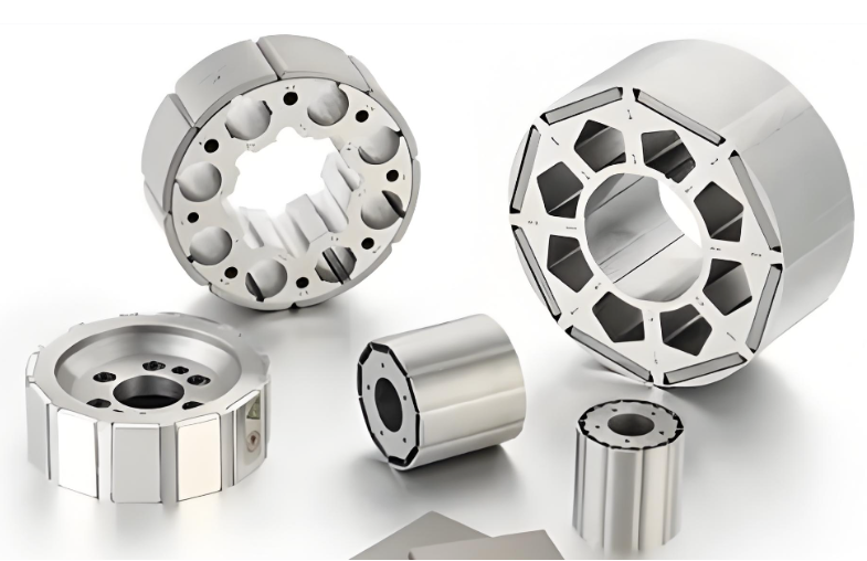
1. Rotor structure comes first. Surface-mounted (SPM) rotors favor arc magnets, whose curved face keeps the air gap uniform. Interior (IPM) rotors take rectangular or trapezoidal magnets, which embed easily and exploit reluctance torque. High-speed machines should favor IPM structures for mechanical strength.
2. Performance needs match material and precision. High torque density and wide speed range point to sintered NdFeB in IPM form. Cost-driven, corrosion-tolerant general duty can use ferrite arc magnets. Operating temperatures above 150 C require high-coercivity NdFeB grades, or a switch to samarium cobalt or alnico, to avoid permanent demagnetization. Hub motors and similar applications that need a flat efficiency curve demand tight control of magnet squareness and dimensional accuracy.
3. Cost and process discipline the choice. High-volume, general-purpose, low-cost production favors equal-radius arc magnets and embedded rectangular magnets: high material utilization and mature processes. Miniature devices and complex circuits suit bonded ring magnets, which need no secondary machining and allow flexible multi-pole magnetization. Sintered radial full rings should be avoided unless the application truly requires them; over-specification is waste.
4. Special duty conditions finalize it. Linear motors take square or parallelogram shapes. High-vibration, high-centrifugal-force machines favor IPM magnets, possibly with banding reinforcement. Humid or corrosive environments call for corrosion-resistant ferrite, or passivated and coated NdFeB.
Material and magnetization method complete the picture: NdFeB versus ferrite, single-pole versus multi-pole, radial versus parallel magnetization all interact with the shape decision.
Quality control: two metrics that decide motor consistency
Beyond shape selection, two magnetic metrics decide whether the motor performs as designed, and they are the industry's quality-control focus.
1. Magnetic field uniformity. Surface field measurement of the magnet verifies magnetization state, pole layout, and material consistency against the design. Deviations appear directly as torque ripple and noise.
2. Flux consistency. The magnet is the motor's field source. Variation in flux from magnet to magnet directly causes vibration, reduced power, and lower efficiency. Industry practice for demanding applications controls flux consistency within 5 percent, 3 percent, or even 2 percent, depending on customer requirements. Achieving those numbers is a production problem: it requires consistent magnet geometry, consistent magnetization, and measurement on every rotor, not sampling.
What the magnet choice means for your assembly line
Whatever shape you choose, the line must solve four handling problems that manual assembly solves badly:
1. Separation. Magnetized magnets stick together in stacks. Feeding them one at a time requires mechanical separation that does not chip edges — and brittle arc and laminated shapes chip easily.
2. Orientation and polarity. The station must detect and enforce polarity before insertion, because a bonded rotor with one reversed magnet cannot be economically reworked.
3. Controlled insertion. A magnet entering a steel slot accelerates suddenly. Uncontrolled insertion is where chipping and injuries happen. The machine must present the magnet into the slot at controlled speed and position, and shape matters: rectangular magnets for IPM slots and curved magnets for SPM surfaces need different fixtures.
4. Magnetize before or after assembly. Pre-magnetized assembly saves a magnetizing step but makes every handling problem harder. Post-assembly magnetization handles the rotor unmagnetized and charges it on the line, simplifying feeding but requiring a magnetizing machine sized for the pole count and field requirement. The choice is driven by magnet strength, rotor size, and volume — and it determines which stations the line needs.
These requirements are why dedicated rotor magnet insertion machines exist: four jobs that punish improvisation.
Questions to answer before choosing a line
1. Which magnet shape, material, grade, and temperature class, and is a second variant planned? 2. What are the magnet dimensions, tolerances, and coating? 3. SPM or IPM rotor structure, and what is the slot or surface geometry? 4. Pre-magnetized magnets, or magnetizing equipment on the line? 5. Target output per hour, and how many rotor models share the line? 6. Which checks must be recorded: polarity confirmation, insertion force, flux consistency after magnetizing?
Frequently asked questions
Q: Which magnet shape is best for a surface-mounted rotor? A: Arc or tile magnets. The curved face keeps the air gap uniform and the field stable. They require precision grinding, but they are the standard for SPM motors.
Q: When should I choose rectangular magnets? A: When the rotor is interior-magnet (IPM) or cost is the priority. They are easy to machine, embed, and assemble in volume, at the cost of slightly higher flux harmonics.
Q: What does the letter suffix on an NdFeB grade mean? A: The maximum operating temperature. Standard grades handle about 80 C; H, SH, UH, and EH raise the limit progressively toward 200 C. Choosing a class below the rotor's real temperature causes permanent demagnetization.
Q: Why does flux consistency matter in production? A: Flux variation between magnets translates directly into vibration and efficiency spread between motors. Tight flux consistency requires consistent magnets, consistent magnetization, and per-rotor measurement.
Q: Is it safer to assemble pre-magnetized magnets? A: It simplifies the line electrically but complicates handling, because charged parts attract steel tools and each other. Post-assembly magnetization is usually easier to automate at higher volumes.
Q: What happens if one magnet is inserted with reversed polarity? A: The rotor fails magnetic field testing. In a bonded design there is no economical rework, so the rotor is scrapped. Polarity verification before insertion is the standard prevention.
Building or expanding a permanent magnet motor line? We design turnkey motor assembly lines, from stator winding through rotor magnet insertion, magnetizing, and final testing. Tell us your rotor range, magnet specification, and target output, and we will propose a line configuration.
Related capability: motor assembly line at https://www.ldmotortech.com/en/products/motor-assembly Related capability: motor rotor die casting at https://www.ldmotortech.com/en/products/die-casting